Solar System Classifications: Active, Passive, and Photovoltaic Systems
Learn about the three primary classifications of solar energy systems—active, passive, and photovoltaic—and how each technology captures and utilizes solar energy for heating and electricity generation.
The economic feasibility of solar systems depends on the amount of solar radiation available at a geographic location. Moreover, using various technologies, solar radiation can be converted into useful energy to heat water or space (air) or to generate electricity. In general, solar systems can be categorized into active, passive, and photovoltaic systems.
Active Solar Systems
There are two basic types of active solar systems used for heating: liquid and air.
- The liquid flat-panel systems make use of water or water–antifreeze mixture (in cold climates) to collect solar energy. In such systems, the liquid is heated in a solar collector (Figure 1) and then transferred to a storage system.
- In contrast, air systems heat the air in “air collectors” and transport it to a storage or a designated space using blowers.
Most active solar systems cannot provide adequate heating for both space and hot water needs. Consequently, an auxiliary or back-up heating system is needed.
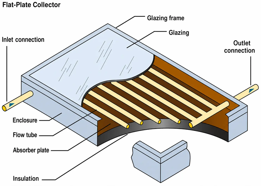
Figure 1 A schematic of a solar collector.
An active solar system makes use of mechanical components such as a collector, pumps, and a storage tank to collect and store solar energy.
The main components of an active liquid hot-water solar system are shown in Figure 2. The solar energy is captured in the flat panel solar collector and then pumped through a heat exchanger where the energy collected is transferred to the domestic hot water (DHW) pre-heater tank and eventually to the auxiliary hot water tank as needed. A home in Golden, Colorado, using a flat-plate solar system is shown in Figure 3.
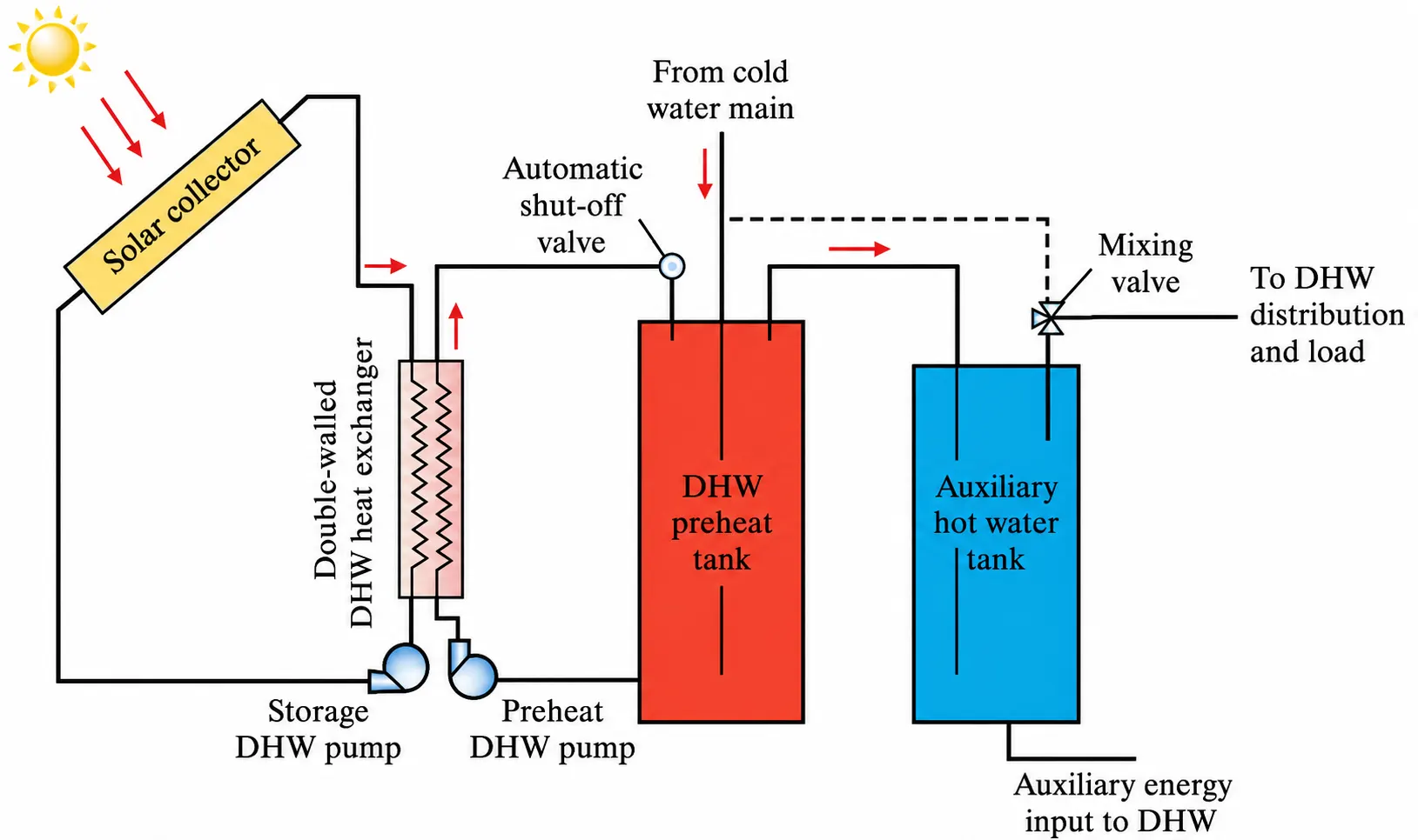
Figure 2 A schematic of a solar hot water system.
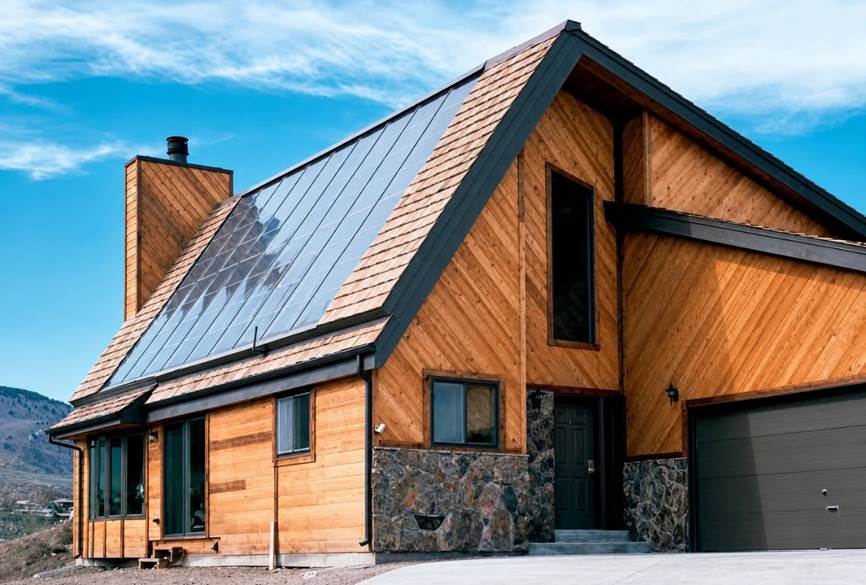
Figure 3 This home in Golden, Colorado, uses a liquid-based solar system for space and water heating.
Evacuated tubes (see Figure 4) are another type of hot-water solar collector that are more expensive and operate at higher temperatures than flat-plate collectors. For these types of collectors, the vacuum inside the tubes minimizes the heat loss from the collector to the surrounding air.
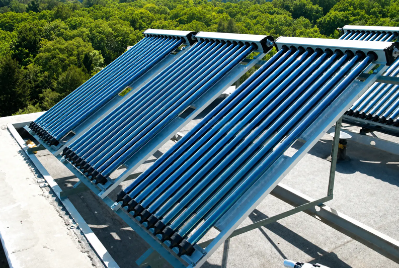
Figure 4 Evacuated-tube solar collectors.
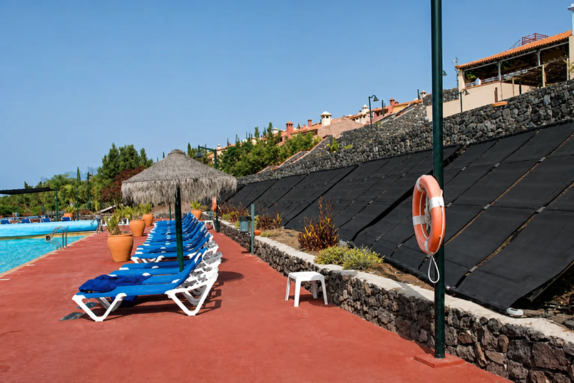
In moderate climates, solar hot-water systems are also used to heat swimming pools. The goal of this type of system is to extend the swimming season. The swimming pool has solar heaters that operate at slightly warmer temperatures than the surrounding air temperature. These types of collectors typically use inexpensive, unglazed, low-temperature collectors made from plastic materials. Because these systems are not insulated, they require large collector areas, approximately 50 to 100 percent of the pool area.
When you travel to the southwestern part of the United States or abroad, you may see parabolic-shaped (U-shaped) collectors with mirror-like surfaces (see Figure 5). These collectors are used to generate electric power in power plants.
Parabolic concentrating systems make use of tracking devices to follow the Sun during the day. In these systems, the rays of the Sun are reflected against solar collectors, which are basically U-shaped mirrors that are connected together inline, to concentrate all the reflected energy onto a receiving pipe that is filled with fluids that have a high heat capacity, such as oil or molten salt.
The concentrated solar energy heats up the fluid, and the energy collected by the fluid in the pipe is then transferred to water to create steam in a heat exchanger. Similar to the conventional steam power plant, the steam then runs through a turbine that turns a generator to create electricity.
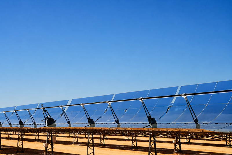
Figure 5 Parabolic (U-shaped) solar collectors.
Example 1
Assume that the 4 flat plate collectors’ system (with dimensions of 1 m × 1.5 m) has an average efficiency of 60 percent during the month of June and is located in Alaska, where 4 kWh/m2/day of solar energy is intercepted by the system. On average, how many gallons of water at 60 °F could be heated to 110 °F by the system each day during the month of June?
$$\text{Total area of the collectors}=(4)(1.0\,\text{m})(1.5\,\text{m})=6\,\text{m}^2$$
$$\text{Total solar energy intercepted by the four collectors each day}=(6\,\text{m}^2)\left(\frac{4\,\text{kWh}}{\text{m}^2\cdot\text{day}}\right)=24\,\frac{\text{kWh}}{\text{day}}=\left(24\,\frac{\text{kWh}}{\text{day}}\right)\left(\frac{3412\,\text{Btu}}{1\,\text{kWh}}\right)=81888\,\frac{\text{Btu}}{\text{day}}$$
Considering the efficiency of the system, the total available energy becomes
$$\text{Total available energy}=(0.6)\left(81888\,\frac{\text{Btu}}{\text{day}}\right)=49133\,\frac{\text{Btu}}{\text{day}}$$
Each gallon of water has a mass of 8.34 pounds and that one Btu represents the amount of thermal energy needed to raise the temperature of one pound mass (lbm) of water by one degree Fahrenheit (°F). Realizing these facts, we can now solve for the unknown gallons (𝑥) of water in the following manner:
$$\text{Total available energy}=49133\,\frac{\text{Btu}}{\text{day}}=\left(x\,\frac{\text{gallons of water}}{\text{day}}\right)\left(\frac{8.34\,\text{lbm}}{\text{gallon of water}}\right)\left(\frac{1\,\text{Btu}}{(1\,\text{lbm})(1^\circ\text{F})}\right)\left(110-60\right)^\circ\text{F}$$
Solving for x, we get
$$x\approx118\,\frac{\text{gallons of water}}{\text{day}}$$
Therefore, each clear day the given system can provide about 118 gallons of hot water for activities such as bathing or showering.
Passive Solar Systems
Passive solar systems do not make use of any mechanical components such as collectors, pumps, blowers, or fans to collect, transport, or distribute solar heat to various parts of a building. Instead, a direct passive solar system uses large glass areas on the south wall of a building and a thermal mass to collect solar energy. The solar energy is stored in the interior thick masonry walls and floors during the day and is released at night.
In cold climates, passive systems also use insulated curtains at night to cover the glass areas to reduce the heat loss. Another feature of a passive solar system is an overhang to shade the windows during summer, as shown in Figure 6.
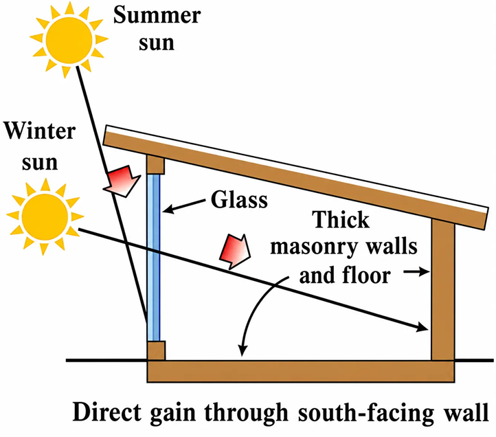
Figure 6 A schematic of a direct passive solar system.
Indirect-gain passive designs use a storage mass placed between the glass wall and the heated space. As the air between the glass and masonry wall is heated, it rises and enters the room through a vent at the top of the wall and is replaced by the cooler room air that enters the lower vent. Not all of the solar heat is transferred to the air; some is stored in the masonry wall or floor (see Figure 7).
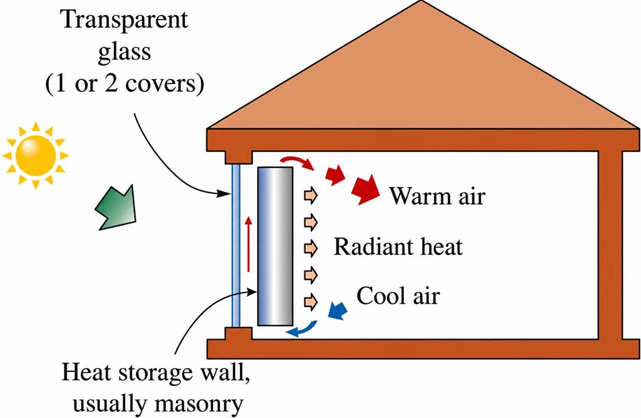
Figure 7 A schematic of an indirect passive solar system.
Another common type of passive solar system is sunspace. The space may be used as a greenhouse, atrium, sun porch, or sunroom. Masonry or concrete floors and walls, water containers, or covered pools of water may serve as thermal storage. A photograph of an interior section of a house with a sunspace is shown in Figure 8.
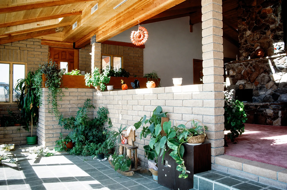
Figure 8 The interior (sunspace) of a passive solar house.
Photovoltaic Systems
A photovoltaic system converts light energy directly into electricity. These systems come in all sizes and shapes, as shown in Figure 9. You have also seen small photovoltaic cells that provide power for a calculator. A larger system that produces power for a home, however, often consists of a photovoltaic array, batteries, a charge controller, and an inverter.
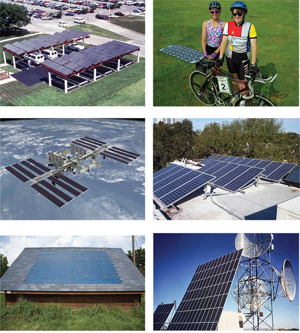
Figure 9 Examples of photovoltaic systems, top row: parking rooftop, solar bike; middle row: space station, a building rooftop; and bottom row: photovoltaic roof shingles, a remote communication facility.
A photovoltaic (PV) cell is the backbone of any photovoltaic system. Photovoltaic cell materials include crystalline, polycrystalline, and amorphous silicon. Crystalline and polycrystalline silicon PV cells have high efficiencies; however, they are expensive to produce.
On the other hand, the amorphous silicon cells have lower efficiencies, are less expensive to produce, and are easier to work with. Thin-film amorphous silicon solar cells can be affixed directly to a metal roof of a building. The efficiencies of various solar cells and the improvements that have been made since 1976 are shown in Figure 10.
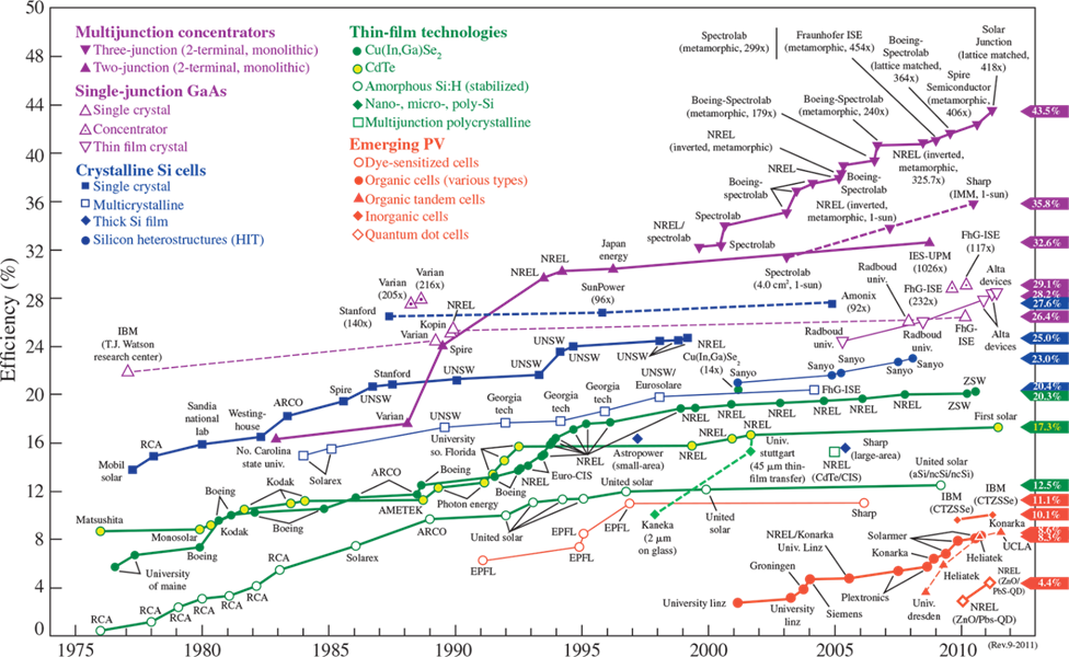
Figure 10 The efficiency of solar cells and how improvements have been made over time.
A typical photovoltaic system consists of a photovoltaic array, batteries, a charge controller, and an inverter.
The manufacturers of photovoltaic systems combine cells to form a module, and then the modules are combined to form what is known as a photovoltaic array (see Figure 11). Photovoltaic systems are classified as stand-alone, hybrid, or grid-tied.
- The systems that are not connected to a utility grid are called stand-alone and require batteries to store the electrical energy to be used during nights and cloudy days.
- Hybrid systems are those that use a combination of photovoltaic arrays and some other form of energy, such as diesel generation.
- As the name implies, grid-tied systems are connected to a utility grid. A grid-tied system does not need a battery bank to store energy. A schematic diagram for a grid-tied system is shown in Figure 12.
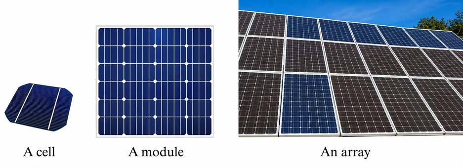
Figure 11 A photovoltaic cell, module, and array.
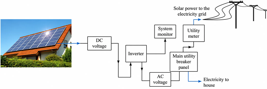
Figure 12 An example and a schematic drawing of a grid-tied PV system.
The electricity that is generated by photovoltaic panels is direct current (DC). Every photovoltaic system has an inverter. An inverter is a device that converts direct current into alternating current that is used in homes. As shown in Figure 12, the line coming out of the inverter goes to the main utility breaker panel in the house, and from there it goes to the utility meter and the electricity grid.
Systems that use batteries to store electricity for cloudy days also make use of a charge controller. A charge controller protects the batteries from overcharging. When the batteries are fully charged, the charge controller disconnects them from the PV array.
Photovoltaic systems are also used in photovoltaic power plants, which represent large-scale commercial systems that produce electricity. One of the largest grid-tied photovoltaic power plants in the United States is the Alamosa photovoltaic plant, which is located in an area of 82 acres in south central Colorado. It went online in 2007 and generates about 8.2 megawatt (MW) of power.
The U.S. solar data for sizing photovoltaic systems are shown in Figure 13. Examples 3 and 4 show you how to use this information.
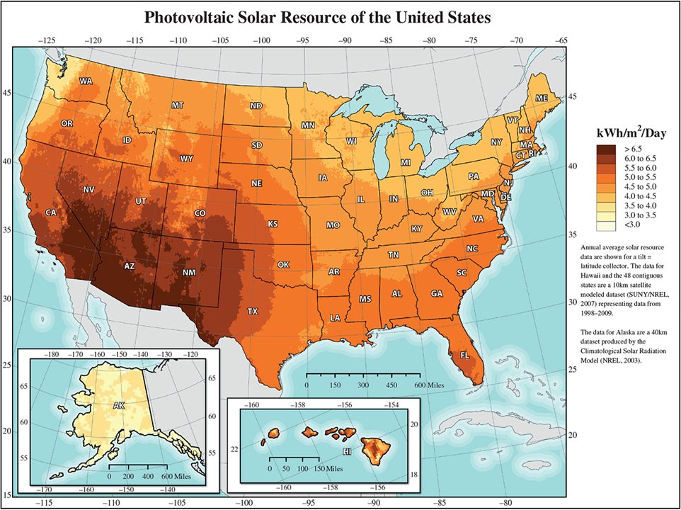
Figure 13 Photovoltaic resources of the United States.
Example 2
A manufacturer of photovoltaic systems provides the following specifications for one of its modules:
$$\begin{aligned}\text{Maximum power} &= 250\,\text{W}\;(\text{at illumination of} 1\,\text{kW}/\text{m}^2)\\A &= 960\,\text{mm}\\B &= 1600\,\text{mm}\end{aligned}$$
What is the efficiency of this module?
$$\text{Efficiency}=\frac{\text{output}}{\text{input}}$$
Note that for this example, the input is 1 kW/m2 or 1,000 W/m2 and the output is 250 W for the entire module. Also, note that
$$\text{Area of the module}=(0.9\,\text{m})(1.6\,\text{m})=1.44\,\text{m}^2$$
Then,
$$\text{efficiency}=\frac{\text{output}}{\text{input}}=\frac{250\,\text{W}}{\left(1000\,\text{W}/\text{m}^2\right)\left(1.44\,\text{m}^2\right)}=0.17\ \text{or}\ 17\%$$
This result represents the maximum possible efficiency of the module under ideal laboratory test conditions. It is important to note that, under real outdoor conditions, the efficiency of the module is less—closer to 13 or 14 percent.
Example 3
As shown in Figure 13, the average solar radiation available for photovoltaic systems for the southern part of Arizona is about 6.5 kWh/m2/day. If a photovoltaic array consists of ten modules (the 250-watt modules from Example 2), each module has dimensions of 0.9 m × 1.6 m, and assuming an efficiency of 14 percent, how much electricity is generated by this system each year?
$$\text{Total area of the photovoltaic system}=(10)(0.9\,\text{m})(1.6\,\text{m})=14.4\,\text{m}^2$$
$$\text{Amount of electricity generated}=(0.14)(14.4\,\text{m}^2)\left(\frac{6.5\,\text{kWh}}{\text{m}^2\cdot\text{day}}\right)\left(\frac{365\,\text{days}}{\text{year}}\right)=4783\,\frac{\text{kWh}}{\text{year}}\approx4800\,\frac{\text{kWh}}{\text{year}}$$
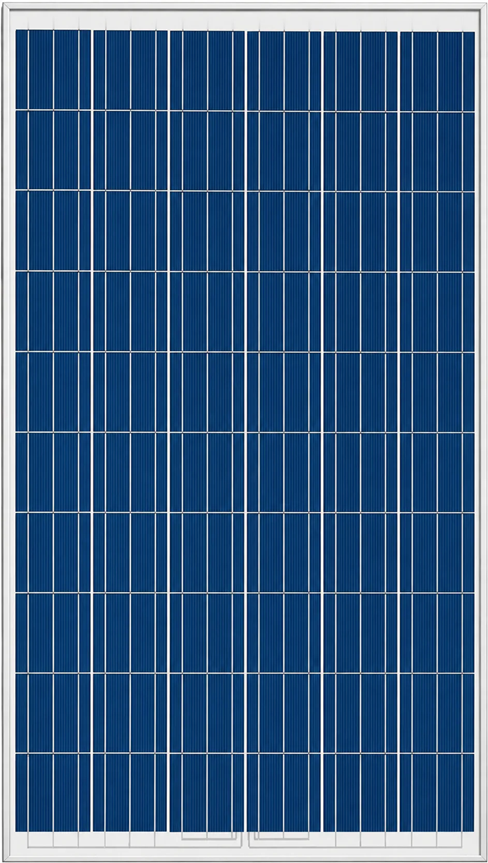
Therefore, this system will generate about 4,800 kWh/year. Note that there are additional losses in the system, depending on the wiring and the inverter, so the amount of electricity that could be consumed would be less than 4,800 kWh/year.
Example 4
How much electricity would be generated if the photovoltaic system of Example 3 is located in Vermont in the northeastern section of the United States?
From Figure 13, the average solar radiation available for Vermont is about 4 kWh/m2/day. Then
$$\text{Amount of electricity generated}=(0.14)(14.4\,\text{m}^2)\left(\frac{4\,\text{kWh}}{\text{m}^2\cdot\text{day}}\right)\left(\frac{365\,\text{days}}{\text{year}}\right)=2943\,\frac{\text{kWh}}{\text{year}}\approx2900\,\frac{\text{kWh}}{\text{year}}$$
Note that the same system in Vermont produces approximately 39 percent less electricity than it would in Arizona.
Key Takeaways
Each solar technology is designed to meet different energy needs and operating conditions, making system selection dependent on factors such as climate, energy demand, installation cost, and available space.
Active solar systems are widely used for domestic hot water, space heating, and concentrated solar power plants, while passive designs improve building energy efficiency through architectural features without consuming electricity.
Photovoltaic systems have become the dominant technology for distributed and utility-scale electricity generation, supporting applications ranging from residential rooftops and off-grid installations to large solar farms integrated with the electrical grid.
Understanding the strengths and limitations of each approach enables engineers to design more efficient, reliable, and economically viable solar energy solutions.