Three-Phase Induction Motor Equivalent Circuit
The analysis of three-phase electric machines is simplified by using their per-phase equivalent circuits. The derivation of an equivalent circuit is based on the consideration of the electromagnetic coupling between the stator and rotor when
- the rotor is stationary and,
- when it is running.
Rotor Stationary
When the rotor of the motor is stationary, the time rate of change of the flux linkages between the stator and the rotor depends on both the number of windings turns in the rotor and the speed and magnitude of the rotating mmf of the stator. This is similar to the transformer action, where the alternating flux of the primary current sets up flux linkages between the primary and secondary windings.
The voltage induced in the secondary winding of a transformer is proportional to the time rate of change of its flux linkages. Similarly, the voltage induced in the rotor winding of a three-phase induction motor is proportional to the time rate of change of the winding’s flux linkages.
The frequency ($f_r$) of the voltage induced in the rotor windings is equal to that of the stator windings. That is,
$$f = f_r \ \ \ \ \ (3.20)$$
where f is the frequency of the stator currents.
The per-phase equivalent circuit of a three-phase induction motor at standstill, then, is similar to that of a transformer. Refer to Figure 3-11(a). The impedance $R_1+jX_1$ represents the per-phase leakage impedance of the stator windings. The impedance $R_c//jX_{\phi}$ represents the per-phase magnetizing impedance of the motor. Because of the air gap between the stator and rotor structures, this impedance is substantially larger than that of a static transformer of equivalent voltage and volt-ampere rating. The impedance ${R_{r}}^{'}+jX{_{r}}^{'}$ represents the per-phase leakage impedance of the rotor windings at standstill.
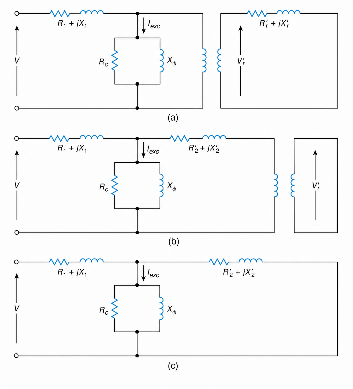
Figure 3-11 Per-phase equivalent circuit of a three-phase motor at standstill: (a) stator and rotor circuits, (b) rotor impedance referred to the stator, (c) equivalent of (b).
The rotor impedance as seen from the stator (Figure 3-11(b)) is
$$Z_2' = a^2\left(R_r' + jX_r'\right) \ \ \ \ \ (3.21)$$
Or
$$Z_2' = R_2' + jX_2' \ \ \ \ \ (3.22)$$
where $Z{_{2}}^{'}$ is the rotor impedance at standstill as seen from the stator, and a represents the number of effective turns between the stator and rotor windings.
The rotor windings are shorted, and thus the ideal transformer shown in Figure 3-11(b) is also shorted. This leads to the per-phase equivalent circuit presented in Figure 3-11(c). The per-phase input voltage to the stator windings and the excitation current are represented, respectively, by V and $I_{exc}$.
Rotor Running
When the rotor is running, the time rate of change of the flux linkage between the stator and rotor windings depends on the relative motion between the synchronously rotating stator mmf and the actual rotor speed.
Since the relative motion between the stator mmf and the rotor speed is given by the slip, the voltage induced in the rotor windings (Vr) is given by
$$V_r = sV_r' \ \ \ \ \ (3.23)$$
where s is the operating slip of the motor and $V{_{r}}^{'}$ is the voltage induced in the rotor windings when the rotor is stationary.
The frequency ($f_r$) of the voltage induced in the rotor windings is related to the frequency (f) of the stator windings by
$$f_r = sf \ \ \ \ \ (3.24)$$
Then the per-phase rotor impedance at a slip s is
$$ Z_r = R_r + jsX_r \ \ \ \ \ (3.25)$$
where $R_r$ and $X_r$ represent the rotor resistance and reactance, respectively. The per-phase equivalent circuit of the motor is shown in Figure 3-12(a). The rotor current ($I_r$) is
$$I_r=\frac{V_r}{Z_r} \ \ \ \ \ (3.26)$$
$$I_r=\frac{sV_r'}{R_r+jsX_r} \ \ \ \ \ (3.27)$$
From the above,
$$I_r=\frac{V_r'}{\dfrac{R_r}{s}+jX_r} \ \ \ \ \ (3.28)$$
Then the per-phase equivalent circuit of the motor can be drawn as shown in Figure 3-12(b).
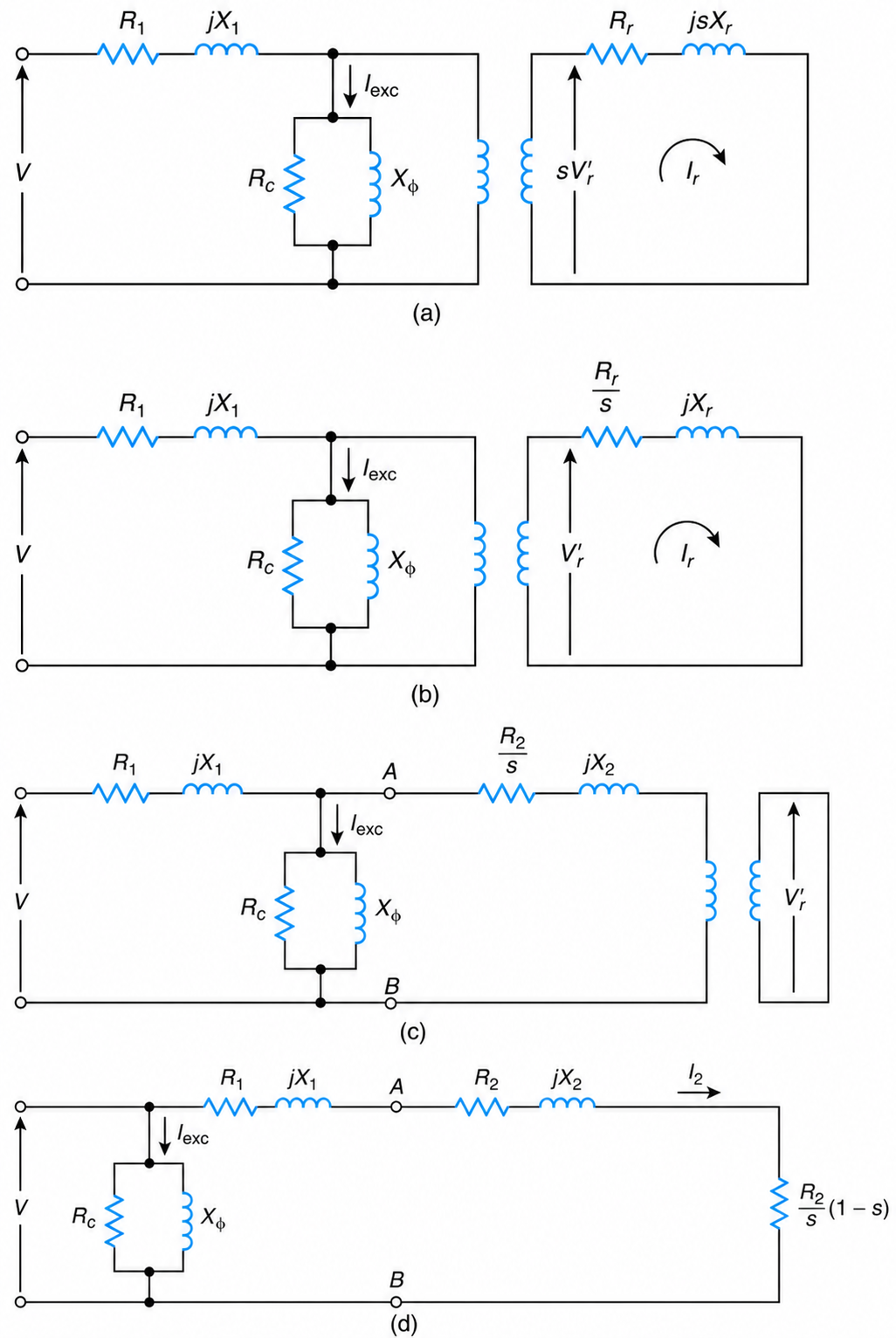
Figure 3-12 Per-phase equivalent circuit of a three-phase induction motor: (a) stator and rotor circuits, (b) equivalent of (a), (c) equivalent of (b), and (d) approximation of (c).
The rotor impedance ($Z_2$) as seen from the stator is
$$Z_2=a^2\left(\frac{R_r}{s}+jX_r\right) \ \ \ \ \ (3.29)$$
Or
$$Z_2=\frac{R_2}{s}+jX_2 \ \ \ \ \ (3.30)$$
The corresponding equivalent circuit is given in Figure 3-12(c).
The real component of the rotor impedance, as seen by the stator, can also be written as follows:
$$\frac{R_2}{s}=R_2+R_2\frac{1-s}{s} \ \ \ \ \ (3.31)$$
The second term on the right-hand side of this equation is the so-called equivalent mechanical load ($R_L$) resistance. That is,
$$R_L=\frac{R_2(1-s)}{s} \ \ \ \ \ (3.32)$$
By assuming that
$$R_2' + jX_2'=R_2 + jX_2 \ \ \ \ \ (3.33)$$
then Figure 3-12(c) represents the general per-phase equivalent circuit of a three-phase induction motor at any speed, as seen from the input terminals of the motor.
When the motor is running, the values of the per-phase rotor resistance ($R_r$) and inductance ($L_r$)are different than when their corresponding values are at standstill ($R{_{r}}^{'},L{_{r}}^{'}$) because of higher temperatures, saturation, and the skin effect.
The skin effect (nonuniform current density within the conductors caused by magnetic flux that passes through them and that varies with time) is of particular importance because it causes the rotor’s circuit resistance and inductance to vary with the frequency of the rotor currents. This variation is significant during starting, but negligible within the speed range of normal load operation. For accurate results, the actual values of the rotor parameters should be used at starting and running conditions.
In order to further simplify the calculations, the magnetizing branch is usually transferred to input terminals of the stator winding, as shown in Figure 3-12(d). The magnetizing impedance could also be represented, as in the case of transformers, by its equivalent series-connected components ($R_{m}+jX_{m}$).